实验任务书
基础实验包:add_16
其实实现64位加法器,我们的思路是:先实现一位加法器,然后实现4位加法器,由4个4位加法器实现一个16位加法器,然后由4个16位加法器实现一个64位加法器。本节实验我采用的是串行进位,当然还有更多的更优化的加法器,例如波形进位等。这里我们暂且不考虑效率。
其实总结起来实现过程,就是——得寸进尺
实现最底层的 4 位加法器(门电路构成)
最底层的其实还不是4位加法器,而是1位加法器,也就是下图:
这张图本身说明的是4位加法器,其中的红色部分就是单独的一个一位加法器。
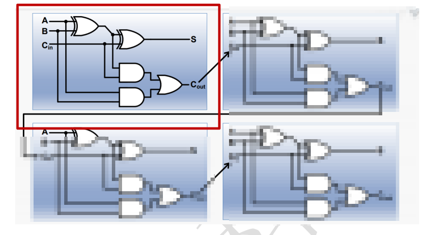
一位加法器的原理非常简单,输入端有 A B Cin,输出端有S 和Cout。
它的逻辑式为:
S = (A ^ B) ^ Cin ;
Cout = ((A ^ B) . Cin) + (A . B) ;
Ps:“.”是与、“+”是或。
使用verilog语言写出:
   // 根据加法器实验结构图写出下面的基本逻辑门
   assign out[0] = a[0]^b[0]^cin;                       // 电路图中的S
   assign temp[0] = (a[0]&b[0])|((a[0]^b[0])&cin);      // 电路图中的Cout
根据下图,复制出4个一位加法器,再将其连接起来:
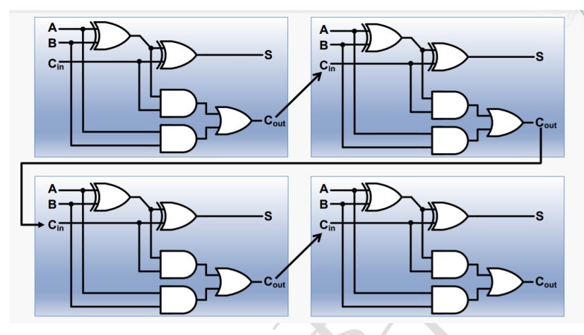
module add_4(a, b, cin, out, cout);
    input [3:0] a;
    input [3:0] b;
    input cin;          // 前一位进位
    output [3:0] out;
    output cout;        // 进位
    wire [3:0] temp;

   // 根据加法器实验结构图写出下面的基本逻辑门
   assign out[0] = a[0]^b[0]^cin;                       // 电路图中的S
   assign temp[0] = (a[0]&b[0])|((a[0]^b[0])&cin);      // 电路图中的Cout

   assign out[1] = a[1]^b[1]^temp[0];
   assign temp[1] = (a[1]&b[1])|((a[1]^b[1])&temp[0]);

   assign out[2] = a[2]^b[2]^temp[1];
   assign temp[2] = (a[2]&b[2])|((a[2]^b[2])&temp[1]);

   assign out[3] = a[3]^b[3]^temp[2];
   assign temp[3] = (a[3]&b[3])|((a[3]^b[3])&temp[2]);

   assign cout = temp[3];

endmodule
现在,已经实现了四位加法器。
由 4 个 4 位加法器串联,构成中层 16 位加法器
`timescale 1ns / 1ps
//////////////////////////////////////////////////////////////////////////////////
// Company:
// Engineer:
//
// Create Date: 2017/10/17 09:52:05
// Design Name:
// Module Name: add_16
// Project Name:
// Target Devices:
// Tool Versions:
// Description:
//
// Dependencies:
//
// Revision:
// Revision 0.01 - File Created
// Additional Comments:
//
//////////////////////////////////////////////////////////////////////////////////


module add_4(a, b, cin, out, cout);
    input [3:0] a;
    input [3:0] b;
    input cin;          // 前一位进位
    output [3:0] out;
    output cout;        // 进位
    wire [3:0] temp;

   // 根据加法器实验结构图写出下面的基本逻辑门
   assign out[0] = a[0]^b[0]^cin;                       // 电路图中的S
   assign temp[0] = (a[0]&b[0])|((a[0]^b[0])&cin);      // 电路图中的Cout

   assign out[1] = a[1]^b[1]^temp[0];
   assign temp[1] = (a[1]&b[1])|((a[1]^b[1])&temp[0]);

   assign out[2] = a[2]^b[2]^temp[1];
   assign temp[2] = (a[2]&b[2])|((a[2]^b[2])&temp[1]);

   assign out[3] = a[3]^b[3]^temp[2];
   assign temp[3] = (a[3]&b[3])|((a[3]^b[3])&temp[2]);

   assign cout = temp[3];

endmodule

module add_16(a, b, cin, out, cout, tmp);
   input [15:0] a;
   input [15:0] b;
   input cin;
   output [15:0] out;
   output cout;
   output [3:0] tmp;
   wire [3:0] temp1;

   add_4 u1_add_4(
                    .a(a[3:0]),
                    .b(b[3:0]),
                    .cin(cin),
                    .out(out[3:0]),
                    .cout(temp1[0])
                    );
   add_4 u2_add_4(
                    .a(a[7:4]),
                    .b(b[7:4]),
                    .cin(temp1[0]),
                    .out(out[7:4]),
                    .cout(temp1[1])
                    );

   add_4 u3_add_4(
                    .a(a[11:8]),
                    .b(b[11:8]),
                    .cin(temp1[1]),
                    .out(out[11:8]),
                    .cout(temp1[2])
                    );
   add_4 u4_add_4(
                    .a(a[15:12]),
                    .b(b[15:12]),
                    .cin(temp1[2]),
                    .out(out[15:12]),
                    .cout(temp1[3])
                    );


   assign cout = temp1[3];
   assign tmp = temp1;

endmodule
扩展方式与之前一样,采用串行进位,只要把对应的线写好就OK。
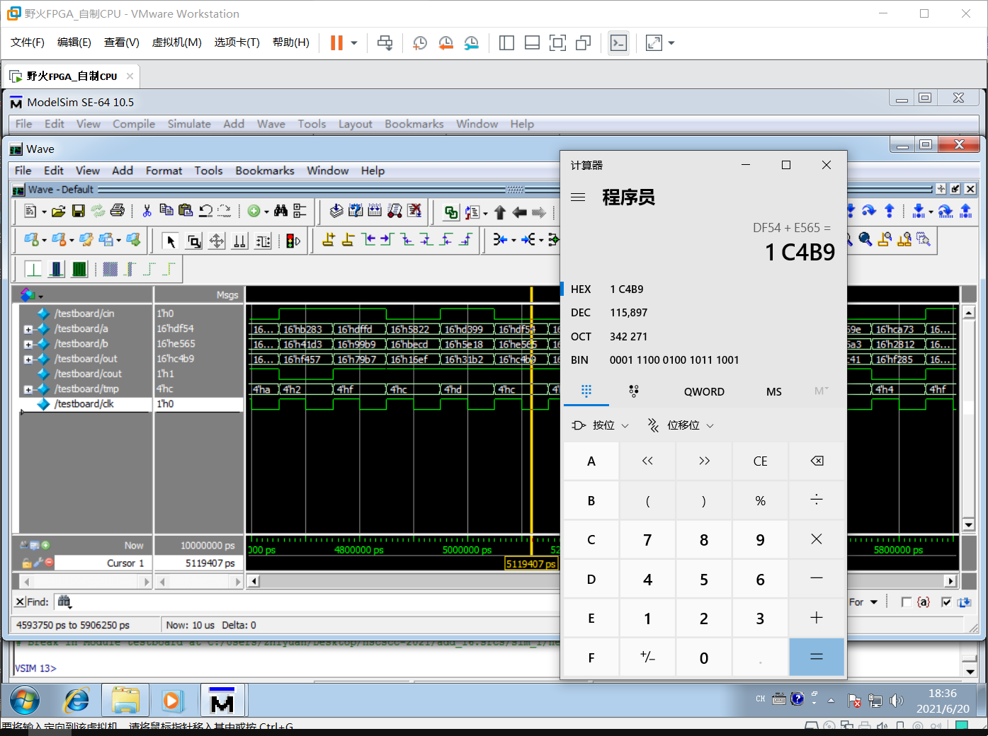
因为实验包已经提供了testbeach文件,我们直接仿真即可:
经过计算器验证,没有任何问题,计算结果正确。
由 4 个 16 位加法器串联,构成上层 64 位加法器
参考文献:
https://www.runoob.com/w3cnote/verilog-expression.html
https://images.app.goo.gl/UPpoGDEoepcnPZF86